As I said in a previous post, the ammeter is epoxied shut, but I found that it chipped off quite easily with a knife. Once the epoxy was off, I flexed the two tabs slightly, and lifted the back off.
 |
| As you may be able to see, the needle is loose inside the face-plate section. Inside the back, there are a few loose pieces that needed reattaching, once I worked out where they went. |
 |
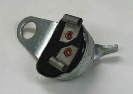
| I left the remains of the needle and its pivot in the case, as they were fine. In the back of the case is the magnet (explained below).
I thought this would be a good time to explain how ammeters actually work, very basically. The needle is attached to a pivot at the bottom of the casing. It can move freely. In the back of the casing is a magnet, as you can see above, so that when there is no current flowing, the needle moves back to the centre. When current is flowing, an electromagnetic field is induced in the coil, soldered to the two terminals on the back, which moves the needle. The more current, the stronger the field, and the further the needle moves.
There is a second pivoting arm at the top of the case, which is the part that is loose above. It has a fork at the end, which fits around a tiny protruding pin on the pivoting bow-tie shaped piece at the bottom, that has the needle attached. Hopefully this incredibly high resolution picture explains how it all fits together. You may want to click on it to see it a bit bigger. We could only guess that this second pivoting piece was some sort of damper, to control vibration.
|
 |
| The pivoting piece on the left is what the needle attaches to, and the one on the right is the one mentioned above. |
Once repaired, it is then very easy to put back together. Put the pivoting pin into the hole in the anti-vibration thing mentioned above. On the back of the casing are two tiny screws. These adjust the distance between the two sides of the pivot, because in the end of the screw is a depression, which the end of the pivot sits in. loosen this off before reassembly. Lift the arm and pivot as one piece into the casing, and seat the bottom of the pivot in the top of the screw. Then, while gently holding the pivot vertical so it located with the top, carefully tighten the screw until it is held in. Hook the fork at the end of the arm over the pin on the needle assembly. Now, gently move the needle back and forth slightly. If you find that the hook rises over the pin and doesn't stay located, then remove the arm and pivot you just put in, take the pivot out, turn the arm piece over, and reassemble. One way over it works nicely, and the other, the hook end rises up.
It may be worth putting a small blob of epoxy over the head of the adjusting screw, so it doesn't vibrate loose and break the ammeter again. Once the internals are put back together, put the back and front back together. It is then probably a good idea to test it, before epoxying the casing back together. Voila! A working ammeter.
I realise that I haven't actually fixed mine yet, but I haven't had time with exams. I have a busy couple of weeks, so I won't be able to do any work for a bit, but I will continue once I have time again.


