 |
| The connecting block (in my fingers) and to the right, the brass connecting "bullet". |
So, I have repaired the broken wire; it was a simple soldering job. The before and after photos are to the right. It was easier than I expected, because the wires have brass "bullets" on the ends, which plug into connecting blocks, so I could solder it separately. You may be able to see the brass "bullet" in the upper photo.
 |
| The repaired wire, plugged into the block. |
Once I repaired the wire, I tested the final wire on the bike, to the brake light. This did not connect, so I have removed the brake switch for further examination. There was only one wire connected, which seems suspicious, and on closer examination, it looks like a connecting tab may have fallen off. While cleaning the switch of the thick layer of grease (it is bolted on to a greasing nipple), the other tab fell off, so it may be a good idea to find a replacement switch. The tab could be soldered on, but I think continued vibration would break the solder joint. There is a blob of solder on the tag already, so clearly it was not a strong enough bond.
 |
| The front of the switch, showing the trigger usually operated by the foot brake lever. |
 |
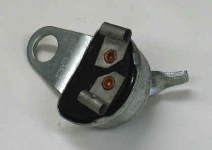
| The back of the switch, showing the two points where tabs would have been connected. Notice the solder blob on the right hand one. |
UPDATE: It is just as I thought, there were originally two connectors on the back, as shown here http://www.britcycle.com/products/391/391_31827_002.jpg It would also appear that new switches are in the region of £30, which seems like a lot to me, but may be worth the money.
Moving on again, to the ammeter.
As shown in the picture below, there was a slight fault that needed sorting out. Dad and I reckoned that the needle had broken off and is somewhere inside, shorting out.
I have managed to chip off the epoxy, and have opened the ammeter up. As expected, the needle is still there, so just needs reattaching. At the bottom is a picture of the two halves.
 |
| If you are really observant, you might notice a minor fault. There's no needle. |
 |
| The back, which appears to have been epoxied shut. |
 |
| The two halves of the ammeter. The needle can be seen loose inside the front, as seen on the left. |
No comments:
Post a Comment