Friday, 18 May 2012

Ammeter

The bike has  Lucas ammeter, which has a broken needle. I trawled the internet for quite a while, and could not find any information at all as to how they worked, what they looked like inside, or how to repair them. This page, therefore, should be helpful to anyone else on the internet who is trying to fix an ammeter, as I will share the knowledge I have gleaned from my attempt at repair.

As I said in a previous post, the ammeter is epoxied shut, but I found that it chipped off quite easily with a knife. Once the epoxy was off, I flexed the two tabs slightly, and lifted the back off.
As you may be able to see, the needle is loose inside the face-plate section. Inside the back,
there are a few loose pieces that needed reattaching, once I worked out where they went. 
I started by taking out the loose pieces, a swinging counterweight thing, and a very tiny pin, which is the pivot. I then undid the two nuts on the back, used as terminals to wire it in, then removed the coil and the plate under it. Below is a picture of all the pieces laid out.


I left the remains of the needle and its pivot in the case, as they were fine. In the back of the case is the magnet (explained below).


I thought this would be a good time to explain how ammeters actually work, very basically. The needle is attached to a pivot at the bottom of the casing. It can move freely. In the back of  the casing is a magnet, as you can see above, so that when there is no current flowing, the needle moves back to the centre. When current is flowing, an electromagnetic field is induced in the coil, soldered to the two terminals on the back, which moves the needle. The more current, the stronger the field, and the further the needle moves. 

There is a second pivoting arm at the top of the case, which is the part that is loose above. It has a fork at the end, which fits around a tiny protruding pin on the pivoting bow-tie shaped piece at the bottom, that has the needle attached. Hopefully this incredibly high resolution picture explains how it all fits together. You may want to click on it to see it a bit bigger. We could only guess that this second pivoting piece was some sort of damper, to control vibration. 

The pivoting piece on the left is what the needle attaches to,
and the one on the right is the one mentioned above. 

Once repaired, it is then very easy to put back together. Put the pivoting pin into the hole in the anti-vibration thing mentioned above. On the back of the casing are two tiny screws. These adjust the distance between the two sides of the pivot, because in the end of the screw is a depression, which the end of the pivot sits in. loosen this off before reassembly. Lift the arm and pivot as one piece into the casing, and seat the bottom of the pivot in the top of the screw. Then, while gently holding the pivot vertical so it located with the top, carefully tighten the screw until it is held in. Hook the fork at the end of the arm over the pin on the needle assembly. Now, gently move the needle back and forth slightly. If you find that the hook rises over the pin and doesn't stay located, then remove the arm and pivot you just put in, take the pivot out, turn the arm piece over, and reassemble. One way over it works nicely, and the other, the hook end rises up. 

It may be worth putting a small blob of epoxy over the head of the adjusting screw, so it doesn't vibrate loose and break the ammeter again. Once the internals are put back together, put the back and front back together. It is then probably a good idea to test it, before epoxying the casing back together. Voila! A working ammeter. 

I realise that I haven't actually fixed mine yet, but I haven't had time with exams. I have a busy couple of weeks, so I won't be able to do any work for a bit, but I will continue once I have time again. 

Friday, 11 May 2012

Session 3: Electrics Continued


The connecting block (in my fingers) and
 to the right, the brass connecting "bullet". 

So, I have repaired the broken wire; it was a simple soldering job. The before and after photos are to the right. It was easier than I expected, because the wires have brass "bullets" on the ends, which plug into connecting blocks, so I could solder it separately. You may be able to see the brass "bullet" in the upper photo.

The repaired wire, plugged into the block. 


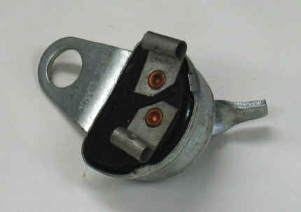
Once I repaired the wire, I tested the final wire on the bike, to the brake light. This did not connect, so I have removed the brake switch for further examination. There was only one wire connected, which seems suspicious, and on closer examination, it looks like a connecting tab may have fallen off. While cleaning the switch of the thick layer of grease (it is bolted on to a greasing nipple), the other tab fell off, so it may be a good idea to find a replacement switch. The tab could be soldered on, but I think continued vibration would break the solder joint. There is a blob of solder on the tag already, so clearly it was not a strong enough bond.


The front of the switch, showing the trigger usually operated by the foot brake lever.
The back of the switch, showing the two points where tabs would have been connected. Notice the solder blob on the right hand one. 

UPDATE: It is just as I thought, there were originally two connectors on the back, as shown here http://www.britcycle.com/products/391/391_31827_002.jpg  It would also appear that new switches are in the region of £30, which seems like a lot to me, but may be worth the money. 


Moving on again, to the ammeter. 

As shown in the picture below, there was a slight fault that needed sorting out. Dad and I reckoned that the needle had broken off and is somewhere inside, shorting out. 

I have managed to chip off the epoxy, and have opened the ammeter up. As expected, the needle is still there, so just needs reattaching. At the bottom is a picture of the two halves. 
If you are really observant, you might
notice a minor fault. There's no needle.
The back, which appears to have
been epoxied shut. 


The two halves of the ammeter. The needle can be seen loose inside the
front, as seen on the left. 

Sunday, 29 April 2012

Session 2 - Electrics

Right, I have just finished another session, although it is more of a continuation of Friday evening's. This time, I was working without Dad's supervision, now I know what I'm looking at. I removed the ammeter, ready for fixing separately, and took off the oil tank so I could access the ignition switch. Then, I tested every wire on the whole bike against a circuit diagram. Everything is connected as it should be, although there is one broken joint and one wire that needs replacing.

It is a testament to how simple and yet effective old British engineering was, that I can even do this at all. On a modern bike, one would have no hope of even finding the wires, let alone being able to check that everything is connected correctly. Here's a picture of the bike with the oil tank removed as well.

Saturday, 28 April 2012

Session 1: Assessing Jobs

I have finally got underway, and have done one session now. I have assessed the whole bike, and this is the list of things that need fixing.

Frame and Forks:
  • paintwork good, stove enamelled in 1980
  • oil seals need replacing
Painted panels, mudguards and fuel tank:
  • fuel tank, oil tank, battery cover and centre panel need respraying - need to identify original colour
  • rust in fuel tank
  • badges and transfers need applying
  • all badges missing, we have some of them
  • tank missing badges and kneepads
  • original seat is in serviceable condition, might be worth getting a new one to protect the original
  • rear mudguard - need to decide whether to repair and paint, or replace
  • front chrome mudguard needs new stays and mounting brackets are broken
Other:
  • stand and foot rest at wrong angle
  • passenger footrests jammed
  • restore and refit front number plate
  • new kickstart rubber needed
  • replace tyres
Electrics and Instruments:
  • ammeter needle broken off inside
  • there is understood to be an igniton fault
  • needs new battery
  • sort out how battery clip works/get new one
  • may not be original speedo
  • mileometer doesn't work
  • complete wiring trace and test
  • ignition - reface/replace points and maybe condensor
Engine:
  • drain oil and remove gear cover and selector shaft - source and replace along with lever
  • top of carburettor loose
  • ensure piston is free
  • adjust tappets, points etc.
  • refill oil, gearbox oil and clutch oil
  • perform routine maintenance checks
I have also taken the tank and seat off, and removed the headlight, so I am ready to start doing the electrics next week. I have learnt what all the parts are called now, and have a copy of the wiring layout, so I should be good to go.

Seat and tank removed

Sunday, 15 April 2012

I've finally got the go-ahead, so hopefully I will begin work before long, although it may get delayed by exams...

Sunday, 8 April 2012

I've written a timeplan, although once I've started it may be adjusted a fair bit. With any luck, I'll be able to start work very soon, once I get some feedback from my D of E leader to make sure it will count. As always, click to enlarge, although right clicking and opening it in a new window/tab may be easier to read.

Tuesday, 13 March 2012

Jobs to do

I've done some thinking, and here is a list of all the jobs that need doing (so far!).

clean rust out of fuel tank
sort out electrical fault
fix ammter needle
fit new front mudguard stay
fit new battery
fix loose carburettor top, and clean carburettor
change rear mudguard
replace gear selector and shaft
repaint bodywork
replace kickstart rubber
fix on front numberplate

That's it for now! It seems like a long list, but hopefully it will go down fairly quickly (famous last words).